aruco_markers
![]()
The aruco_markers package is a compact Python toolkit designed to manage ArUCo markers. It serves as a streamlined interface for the OpenCV aruco module and offers a range of capabilities through both a command line interface and a simplified library interface. For more information, refer to the accompanying documentation.
- Code: https://github.com/cmower/aruco_markers
- Documentation: https://cmower.github.io/aruco_markers/
- PyPI: https://pypi.org/project/aruco-markers/
- Issues: https://github.com/cmower/aruco_markers/issues
Install
From PyPI
From source
In a new terminal:
- Clone repository:
- (ssh)
$ git clone git@github.com:cmower/aruco_markers.git, or - (https)
$ git clone https://github.com/cmower/aruco_markers.git
- (ssh)
- Change directory:
$ cd aruco_markers - Ensure
pipis up-to-date:$ python -m pip install --upgrade pip
- Install from source:
$ pip install .
The <tt>aruco_markers</tt> library
All the functionality of the library can be accessed via
Full documentation for all the classes/functions provided can be found here.
Command line interface
Several features of the library are exposed to the command line via the aruco command. When running these commands, several directories will be created. The top level directory is ~/aruco_markers_data. All the data created by these commands are stored here, specified in the following sub-sections.
The available commands are
collect: Collect data with checkerboard to calibrate a camera.calibrate: Calibrate a camera.generate: Generate marker tags.detect: Detect marker poses from camera feed.server: Start a camera server.
The use of these commands are described below. In addition, you can access the documentation for ecah command by appending --help. For example
Similarly for each of the other commands.
Generating markers
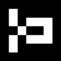
You can generate markers using the aruco generate command. When the --save flag is included in the command line input, the marker data is saved in the ~/aruco_markers_data/tags directory. Two files are created, an image of the marker as a PNG and a printable PDF. The PDF includes the tag and meta information as human-readable text.
For example, try running
The expected output is as follows (note HOMEDIR will be relaced with what ever your home directory is set as).
Note, if you have already run aruco generate before, then it is possible you will not see the lines acknowledging a directories creation (i.e. those starting with Created).
The PNG file created should match the marker displayed at the top of this readme, i.e. here.
The full list of available dictionaries are as follows.
- DICT_4X4_50
- DICT_4X4_100
- DICT_4X4_250
- DICT_4X4_1000
- DICT_5X5_50
- DICT_5X5_100
- DICT_5X5_250
- DICT_5X5_1000
- DICT_6X6_50
- DICT_6X6_100
- DICT_6X6_250
- DICT_6X6_1000
- DICT_7X7_50
- DICT_7X7_100
- DICT_7X7_250
- DICT_7X7_1000
- DICT_ARUCO_ORIGINAL
- DICT_APRILTAG_16h5
- DICT_APRILTAG_25h9
- DICT_APRILTAG_36h10
- DICT_APRILTAG_36h11
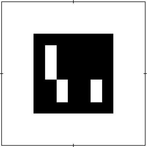
When creating markers, it's often the case you want to affix the printed marker onto an object. In such cases, knowing the mid-points of the rectangle is helpful, as manual measurements can be inaccurate. To simplify this process, you can use the --addhalfmarks flag in the aruco generate command while generating markers. The following is an example of how the output would look like when running this command.
Calibrating a camera
Calibrating a camera can be performed using the aruco collect and aruco calibrate command. Running this command will take you through several steps in order to calibrate the camera.
Prerequisites
You will require a checkerboard to complete the calibration process. A good resource for getting printable checkerboards can be found here. It is a good idea to attach the printed checkerboard to a flat surface.
You can also find a checkerboard in the doc/ directory called Checkerboard-A4-25mm-8x6.pdf. This is a 8-by-6 checkerboard, where each square has length 25mm when printed on A4.
Collect data

To gather data for calibration, execute the aruco collect command. When the checkerboard is detected correctly, a result similar to the one depicted in the above figure should appear. Press the ESC key to stop collecting data.
To obtain accurate estimated parameters from the calibration process, it is advisable to move the checkerboard to different depths and orientations on the screen. Keep in mind that a considerable amount of data could be collected, so make sure that your PC has sufficient storage capacity. The quantity of data required is uncertain, but collecting more data will generally result in more precise estimated parameters. Nevertheless, processing more data will take more time. Ensuring sufficient coverage of depths and orientations is important.
In this particular example, I used the Checkerboard-A4-25mm-8x6.pdf found in the doc/ directory for the checkerboard. Since I am using my laptop's webcam, the camera index is 0 (which is the default value). I began the data collection process by executing the following command.
Run $ aruco collect --help if you need more clarity on the command line input variables.
You should expect terminal output similar to the following.
In the above, HOMEDIR is your home directory, i.e. where ever ~/ is on you PC, and CAMERANAME is the camera name used for data collection. This should correspond to the camera you intend to calibrate (if you have more than one camera attached to your PC). Note the CAMERANAME, it will be required in the calibration step next.
All the raw images that contain the checkerboard are collected into a zip file called data.zip. You can run the collection process several times, and the new data is appended to the zip file (the collection does not overwrite previously collected data).
Calibrate camera
Once you have collected data (as described in the previous section), you can directly perform the calibration. All you require is the name of the camera (this was ouput to the terminal during the data collection, see CAMERANAME in previous section).
In my example, I ran the following.
The terminal output should look similar to the following.
In the above, 60 files were successfully processed. Note, each file name is given a unique time stamp so files are not overwritten. The duration of the calibration process is reported and also the estimated parameters. You do not need to note these since they are saved in the camera_parameters.dat file.
If you have a lot of data and the processing is taking too long, you can downsample the data by specifying the --maxfiles MAXFILES flag. This will randomly sample MAXFILES files from the file names (uniform distribution) and then perform the calibration.
View pose detection from a camera feed
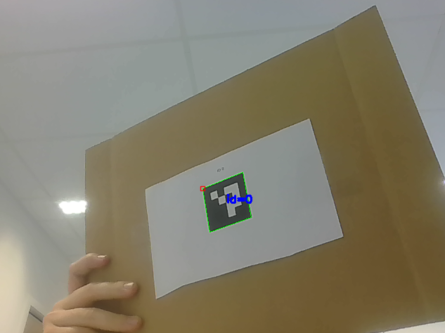
After calibrating a camera, you can use the aruco detect command to display the position of a marker. This function is primarily intended for debugging and serves as a demonstration of detector configuration. However, if the camera has not been calibrated beforehand, this command will throw an error.
When you run aruco detect you should see something similar to the figure above. I ran this example by running the following in terminal.
Note, the marker I use in this example has a length of 5cm. This information is required if you want to use the pose estimation.
Server
You can run a server that will broadcast images to a UDP network. Simply run the following
Several listeners can recieve the feeds from this server. The information flow is as follows.
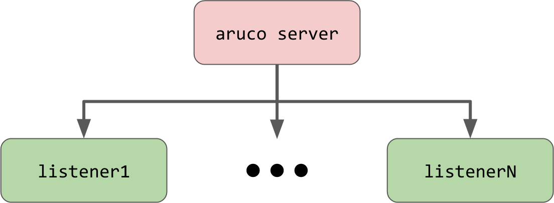
To see this in action try running the example script example/server_listener.py. Note, this script can be run multiple times in separate terminals.
Marker pose estimation
If you opt for the aruco_markers package, you can use the command line interface to produce tags and calibrate cameras. However, if you require additional features, you can customize the class/method structure available in the library. Several methods are provided to that enable you to easily load camera parameters, and estimate marker poses.
Please see the examples, that show how to implement a simple pose estimator into ROS 1/ROS 2. This example assumes you have calibrated your camera by running aruco collect, and aruco calibrate prior to running this script.
Build documentation
The documentation is hosted here. However, if you would like to build the documentation yourself, follow these steps.
In a new terminal:
- Clone repository:
- (ssh)
$ git clone git@github.com:cmower/aruco_markers.git, or - (https)
$ git clone https://github.com/cmower/aruco_markers.git
- (ssh)
- Change directory:
$ cd aruco_markers/doc - Generate the main page:
$ python gen_mainpage.py
- Install doxygen:
$ sudo apt install doxygen - Build documentation:
$ doxygen - View documentation:
- In a browser, open
html/index.html - Build pdf (requires LaTeX)
$ cd latex$ make- Open the file called
refman.pdf
- In a browser, open
Supported cameras
Generally, any camera that is accessible by the OpenCV VideoCapture class is supported. Others include
- The ZED-Mini RGBD camera.
Citing
If you use aruco_markers in your work, please consider citing the following.
Contributing
If you have any issues with the library, or find inaccuracies in the documentation please raise an issue. I am happy to consider new features if you fork the library and submit a pull request.